| Home |
| Misc. |
|
12-May-2020 Bertho Boman |
|
|
|
|
Introduction
Here are three ways of adding a pulse output, once per turn, to regular stepper motors, using different assembly methods. In all cases no dimensions are given since they will vary based on the stepper motor and the available opto-interrupter. Opto-Interrupter Information
The resolution (how well-defined the state of change is) depends on the size of the light beam reaching the transistor since it will be gradually blocked by the approaching flag. The smaller the beam, the better the resolution but the weaker the light to drive the transistor. Since almost all opto-interrupters are used with a flag approaching from the side, many opto-interrupters have vertical slots to get better resolution (sharpness of change). In other words, it is important for best performance that the flag is approaching in a direction that will quickly cut off the light beam going through the slots. That is also why it is important that the flag edge is really aligned parallel with the slot. For information on a high accuracy "Home" switch see:
The First Design First a picture of a stepper motor's recessed rear shaft: 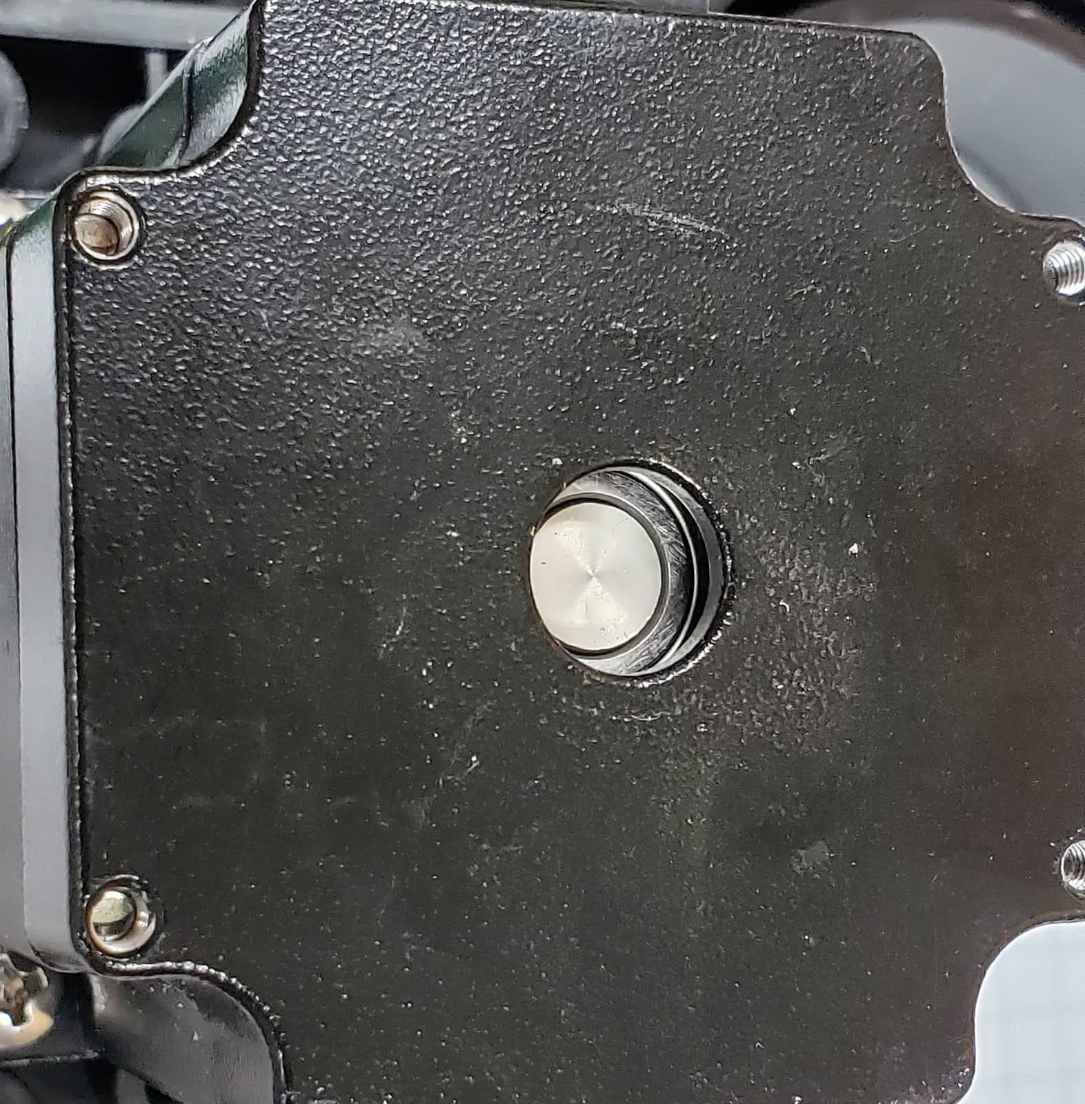 Adding a Flag: 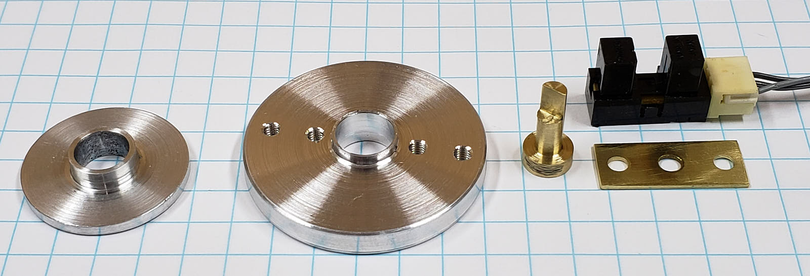 To make it easier to accurately glue the shaft extension to the recessed shaft, I made a simple little guide that just fits into the hole in the back of the stepper and has a center opening slightly larger than the base of the shaft extension. It is used to align the shaft extension when it is glued to the shaft. See item number 1 (left) in the picture. Clean the end of the stepper shaft and the shaft extension with a cotton swab (Q-Tip) dipped in acetone or other cleaner. Add a very small drop of super-glue to the shaft extension and slide it through the guide and then press it down for about 20 seconds. Do not disturb it for a minute and then remove the guide. Test run the stepper to verify that the shaft extension is glued properly. Congratulation! You now have a stepper with a shaft mounted flag. Adding the Base: Several drops of super-glue is placed on the back and it simply glued to the back of the stepper and is let to cure for a minute or so. Adding the Opto-Interrupter: Wire the opto-interrupter as normally done with a resistor driving the LED and a pull-up resistor on the transistor collector. The values depend on the opto-interrupter brand and the circuit interfaced to. Typical values would be 220 Ohm for the LED resistor and 4.7 kOhm for the transistor assuming a 5 Volt supply. Aligning the Opto-Interrupter: It can also be done using a volt meter and turning the stepper very slowly. Even just an LED could be used to see the status. Here is a CAD model of the assembly: 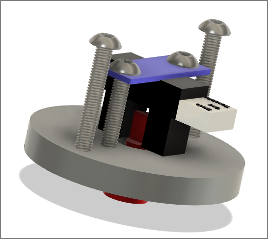 Adding a Cover: 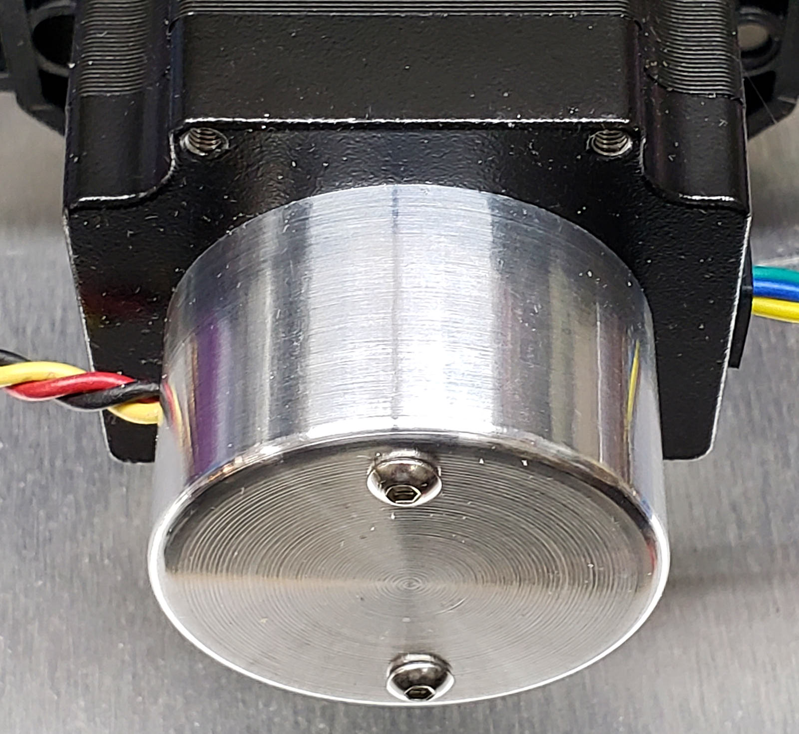 The Second Design If no machining equipment is available or there is a rush, a much simplified version can be made. Please read the above section first to better understand this simplified part. Adding a Flag: 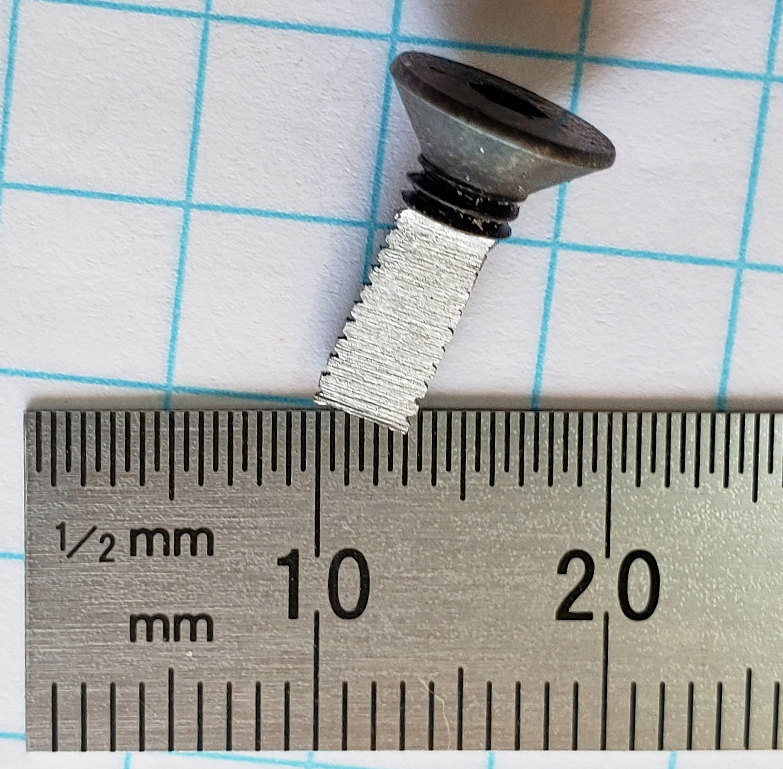 It is super-glued to the shaft without a guide. Run the stepper to see if it was mounted successfully. If not, start over. Adding the Opto-Interrupter: 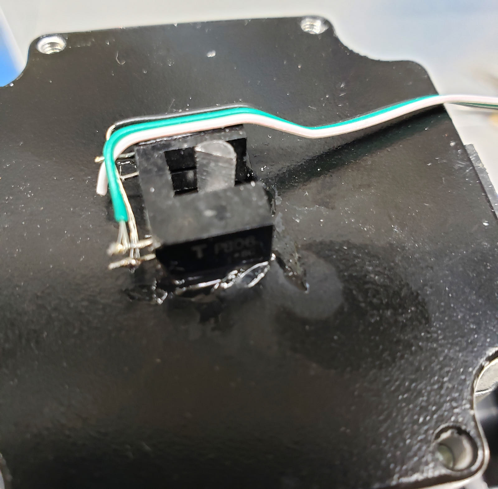
I am sorry for the poor picture quality! Adding a Cover: 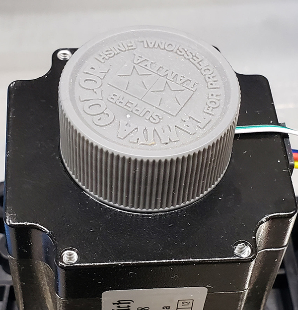 The Third Design A third option, in this line of glued on shaft extensions, would be to glue on a straight short shaft that would stick out about 8mm (depends on the opto-interrupter) and at the end glue on a horizontal flag to extend out about 15mm. The opto-interrupter was then mounted with the legs pointing toward the shaft and adjusted so that the flag's edge was parallel with the opto-interrupter slot. The opto-interrupter was glued with one leg to the back of the stepper motor. This style gives very good resolution since the flag movement is much larger and therefore goves a sharper transition. 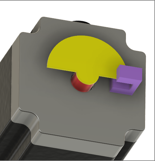
The flag was cut from an old credit card. It is a suitable 0.8mm thick. The shape is not important except the edges should be pointing to the center of the shaft to match the opto-interrupter's slot. The two resistors were glued down to make it self-contained. A cover was also added afterwards. 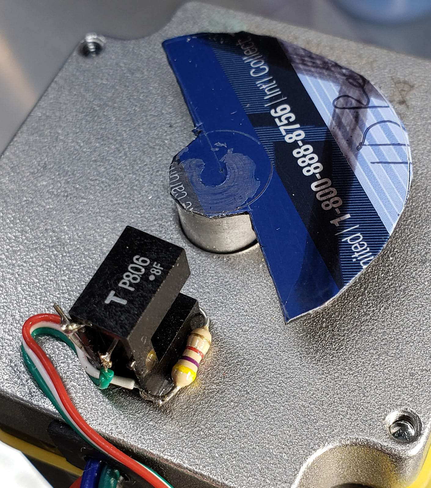 Comparison of the Three Types The blue top trace is from a stepper using the first type and the yellow bottom trace is from the second one. As expected, the first one has much "cleaner" transitions, faster fall and rise times which in turn translates to better definition of the reference point. 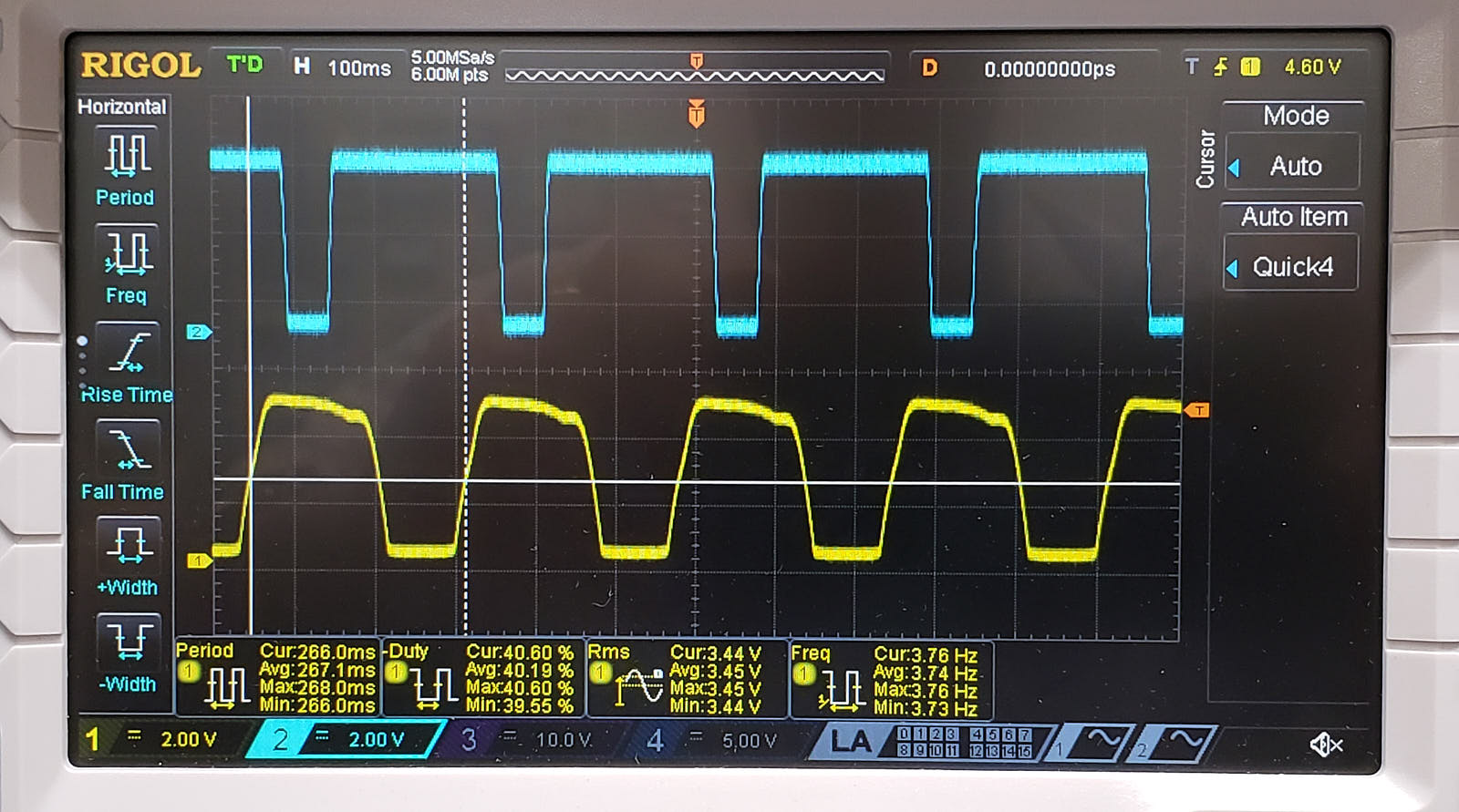 The display below is from testing the third type. As predicted, this third version has even faster rise and fall times. It is also the easiest one to make although physically bigger. 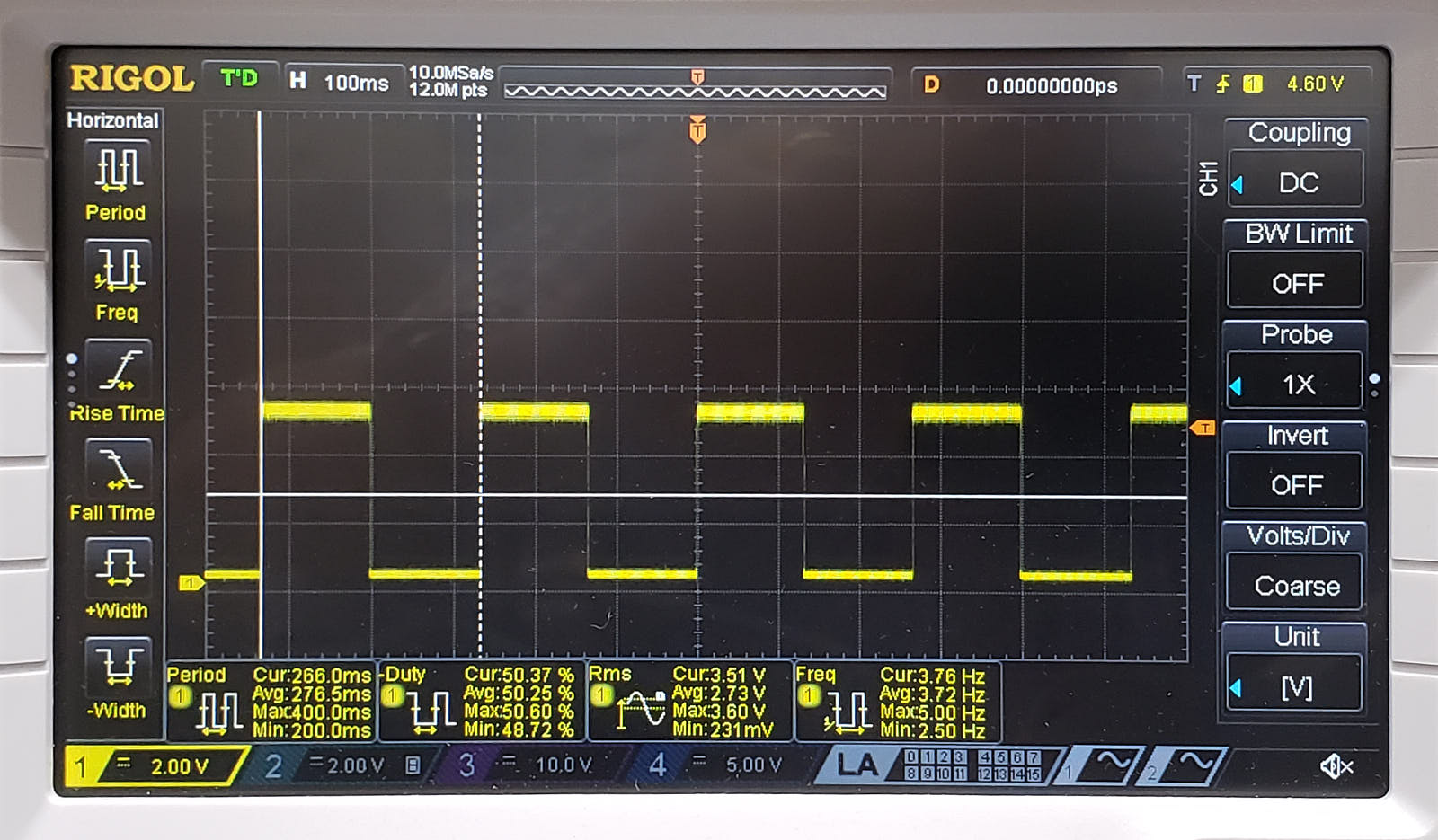 Summary: Bertho Boman
|